ESP32 C1101 433MHz Demo
This tutorial demonstrates how to set up and use the C1101 433MHz RF module with an ESP32 board using PlatformIO in Visual Studio Code.
Requirements
- ESP32 development board (e.g. ESP32-S3)
- C1101 433MHz RF module (e.g. Amazon link)
- Jumper wires
- Visual Studio Code with PlatformIO extension installed
Wiring the C1101 to ESP32
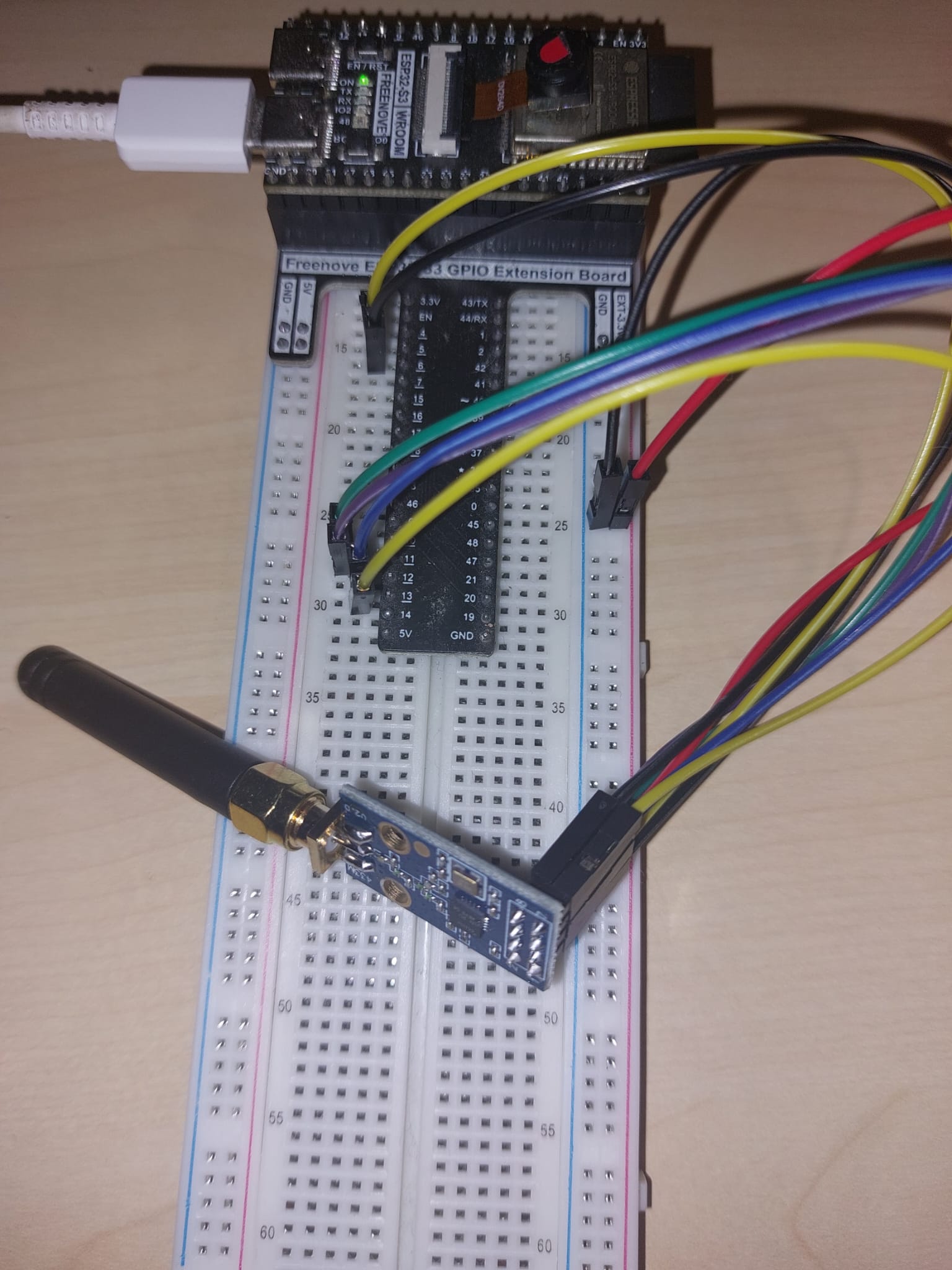
Connect the C1101 module to the ESP32 as follows:
| C1101 Pin | ESP32 Pin |
|---|---|
| VCC (2) | 3.3V |
| GND (1) | GND |
| SCK (5) | GPIO12 (SCK) |
| M0SI (6) | GPIO11 (MOSI) |
| MOSI (7) | GPIO13 (MISO) |
| CS (4) | GPIO10 (SS) |
| GDO0 (3) | GPIO4 |
| GDO2 (8) | Not connected |

PlatformIO Project Setup
CC1101_Transmitter
- Follow the steps in the Configure platformio for ESP32 tutorial to set up a new PlatformIO project for your ESP32 board.
- Call this project
CC1101_Transmitter - Install the necessary libraries for C1101 communication. Add the following lines to your
platformio.inifile under the[env:freenove_esp32_s3_wroom]section:
lib_deps =
    https://github.com/LSatan/SmartRC-CC1101-Driver-Lib
- Create a new file named
C1101_transmitter.cppin thesrcfolder of your project and add the following code:
// New transmission method.
// In addition, the gdo0 and gdo2 pin are not required.
// https://github.com/LSatan/SmartRC-CC1101-Driver-Lib
// by Little_S@tan
#include <ELECHOUSE_CC1101_SRC_DRV.h>

byte transmit_byte[12] = {72, 101, 108, 108, 111, 32, 87, 111, 114, 108, 100, 49};
char* transmit_char = "Hello World2";

void setup() {
  // Pin configuratie voor ESP32-S3
  // SCK: 12, MISO: 13, MOSI: 11, SS: 10
  ELECHOUSE_cc1101.setSpiPin(12, 13, 11, 10);

  Serial.begin(115200);

  if (ELECHOUSE_cc1101.getCC1101()) {  // Check the CC1101 Spi connection.
    Serial.println("Connection OK");
  } else {
    Serial.println("Connection Error");
  }

  ELECHOUSE_cc1101.Init();        // must be set to initialize the cc1101!
  ELECHOUSE_cc1101.setCCMode(1);  // set config for internal transmission mode.
  ELECHOUSE_cc1101.setModulation(
      0);  // set modulation mode. 0 = 2-FSK, 1 = GFSK, 2 = ASK/OOK, 3 = 4-FSK, 4 = MSK.
  ELECHOUSE_cc1101.setMHZ(
      433.92);  // Here you can set your basic frequency. The lib calculates the frequency
                // automatically (default = 433.92).The cc1101 can: 300-348 MHZ, 387-464MHZ and
                // 779-928MHZ. Read More info from datasheet.
  ELECHOUSE_cc1101.setSyncMode(
      2);  // Combined sync-word qualifier mode. 0 = No preamble/sync. 1 = 16 sync word bits
           // detected. 2 = 16/16 sync word bits detected. 3 = 30/32 sync word bits detected. 4 = No
           // preamble/sync, carrier-sense above threshold. 5 = 15/16 + carrier-sense above
           // threshold. 6 = 16/16 + carrier-sense above threshold. 7 = 30/32 + carrier-sense above
           // threshold. ELECHOUSE_cc1101.setPA(10);      // set TxPower. The following settings are
           // possible depending on the frequency band.  (-30  -20  -15  -10  -6    0    5    7 10
           // 11   12) Default is max!
  ELECHOUSE_cc1101.setCrc(
      1);  // 1 = CRC calculation in TX and CRC check in RX enabled. 0 = CRC disabled for TX and RX.

  Serial.println("Tx Mode");
}

void loop() {
  // 3 different methods to send data without gdo
  // When sending, we give a little time to completely transmit the message (time in millis).
  // You can shorten the time. It depends on the data rate and the packet length. Just try it out
  // for fine tuning.

  // Transmitt "Hello World" from byte format.
  ELECHOUSE_cc1101.SendData(transmit_byte, 12, 100);
  delay(2000);

  // Transmitt "Hello World" from char format.
  ELECHOUSE_cc1101.SendData(transmit_char, 100);
  delay(2000);

  // Transmitt "Hello World" from char format directly.
  ELECHOUSE_cc1101.SendData("Hello World3", 100);
  delay(2000);
}
- Save the file.
- In a PlatformIO terminal, run the following command to build and upload the code to your ESP32 board:
pio run -t upload
- After the upload is complete, open the Serial Monitor to view the output from your ESP32 board.
CC1101_Receiver
- Create a new PlatformIO project for your ESP32 board and name it
CC1101_Receiver - Install the necessary libraries for C1101 communication. Add the following lines to your
platformio.inifile under the[env:freenove_esp32_s3_wroom]section:
lib_deps =
    https://github.com/LSatan/SmartRC-CC1101-Driver-Lib
- Create a new file named
C1101_receiver.cppin thesrcfolder of your project and add the following code:
// New receiving method. This method checks the Rx Fifo for any data it contains.
// It allows you to do several things in a loop.
// In addition, the gdo0 and gdo2 pin are not required.
// https://github.com/LSatan/SmartRC-CC1101-Driver-Lib
// by Little_S@tan
#include <ELECHOUSE_CC1101_SRC_DRV.h>

void setup()
{
    // Pin configuratie voor ESP32-S3
    // SCK: 12, MISO: 13, MOSI: 11, SS: 10
    ELECHOUSE_cc1101.setSpiPin(12, 13, 11, 10);

    Serial.begin(115200);

    if (ELECHOUSE_cc1101.getCC1101())
    { // Check the CC1101 Spi connection.
        Serial.println("Connection OK");
    }
    else
    {
        Serial.println("Connection Error");
    }

    ELECHOUSE_cc1101.Init();           // must be set to initialize the cc1101!
    ELECHOUSE_cc1101.setCCMode(1);     // set config for internal transmission mode.
    ELECHOUSE_cc1101.setModulation(0); // set modulation mode. 0 = 2-FSK, 1 = GFSK, 2 = ASK/OOK, 3 = 4-FSK, 4 = MSK.
    ELECHOUSE_cc1101.setMHZ(433.92);   // Here you can set your basic frequency. The lib calculates the frequency automatically (default = 433.92).The cc1101 can: 300-348 MHZ, 387-464MHZ and 779-928MHZ. Read More info from datasheet.
    ELECHOUSE_cc1101.setSyncMode(2);   // Combined sync-word qualifier mode. 0 = No preamble/sync. 1 = 16 sync word bits detected. 2 = 16/16 sync word bits detected. 3 = 30/32 sync word bits detected. 4 = No preamble/sync, carrier-sense above threshold. 5 = 15/16 + carrier-sense above threshold. 6 = 16/16 + carrier-sense above threshold. 7 = 30/32 + carrier-sense above threshold.
    ELECHOUSE_cc1101.setCrc(1);        // 1 = CRC calculation in TX and CRC check in RX enabled. 0 = CRC disabled for TX and RX.

    Serial.println("Rx Mode");
}
byte buffer[61] = {0};

void loop()
{

    // Checks whether something has been received.
    // When something is received we give some time to receive the message in full.(time in millis)
    if (ELECHOUSE_cc1101.CheckRxFifo(100))
    {

        if (ELECHOUSE_cc1101.CheckCRC())
        { // CRC Check. If "setCrc(false)" crc returns always OK!
            Serial.print("Rssi: ");
            Serial.println(ELECHOUSE_cc1101.getRssi());
            Serial.print("LQI: ");
            Serial.println(ELECHOUSE_cc1101.getLqi());

            int len = ELECHOUSE_cc1101.ReceiveData(buffer);
            buffer[len] = '\0';
            Serial.println((char *)buffer);
            for (int i = 0; i < len; i++)
            {
                Serial.print(buffer[i]);
                Serial.print(",");
            }
            Serial.println();
        }
    }
}
- Save the file.
- In a PlatformIO terminal, run the following command to build and upload the code to your ESP32 board:
pio run -t upload
- After the upload is complete, open the Serial Monitor to view the output from your ESP32 board.
pio device monitor
- You should see the received messages along with RSSI and LQI values printed in the Serial Monitor whenever the transmitter sends data.
Rssi: -39
LQI: 129
Hello World1
72,101,108,108,111,32,87,111,114,108,100,49,
Rssi: -40
LQI: 129
Hello World2
72,101,108,108,111,32,87,111,114,108,100,50,
Rssi: -40
LQI: 130
Hello World3
72,101,108,108,111,32,87,111,114,108,100,51,
Conclusion
You have successfully set up and tested the C1101 433MHz RF module with an ESP32 board using PlatformIO in Visual Studio Code. You can now start developing your own applications for wireless communication using the C1101 module.